Contact
 Andy's Parts Smarts
 Cart
Cart

F-Body Buyer's Guide
FENDERS
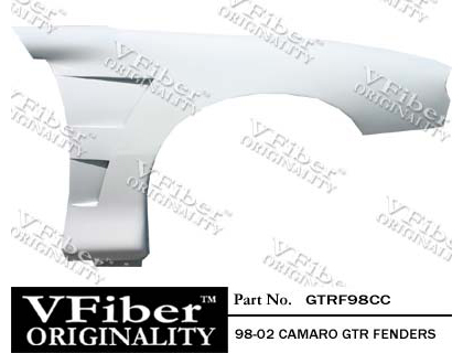
Vision Auto
Fiberglass Fenders - GTR Style
Looking to improve the looks, performance and fuel efficiency of your Camaro,parts such as this lightweight fender from Vision Auto are sure to help. By reducing weight on the notoriously front-heavy Camaro, steering sensations are sharpened, turn in is more immediate, and braking is improved slightly. In addition, the hot air from the wheel wells is dissipated through the rear-facing fender vents which are as functional as they are good looking. This trick accessory is available through Andy's Auto Sport for a very reasonable $183.20 for a pair:
CAMARO/FIREBIRD WHEELS
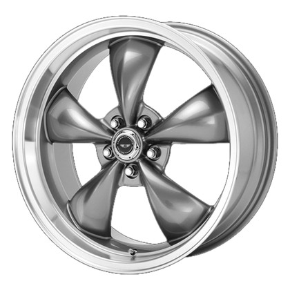
American Racing
Torq Thrust - Anthracite
American Racing needs no introduction, as their wheels are seen on all makes and models of domestic cars, and for good reason. The Torq Thrust wheel utilizes a simple and classic 5-spoke design, with wide, rounded spokes and a nicely polished lip. Whether you just want a new look or you want a set of rims that are lightweight and improve brake cooling, these are perfect for you, and they're available at Andy's Auto Sport for very reasonable prices, for all sorts of muscle cars including Corvettes, Camaros and Firebirds.
HOODS
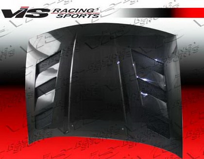
VIS Racing
AMS Style Carbon Fiber Hood
VIS Racing's line of automotive accessories is popular due to their consistency, fit and finish and reasonable pricing. This particular hood is much lighter than stock, which helps improve handling and fuel economy, plus, this AMS hood features venting to reduce underhood temperatures, a must for anybody looking to race their Camaro. In fact, this hood is so light that it's best secured with a set of hood pins, which are available, along with this hood, at Andy's Auto Sport for $744.60 a piece:
HEADERS
JBA
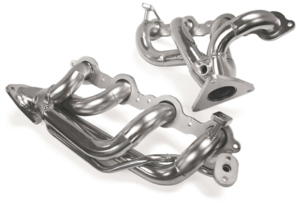
Silver Ceramic Coated Headers
JBA's ceramic coated headers are the perfect upgrade if you're looking for improved throttle response, more torque and horsepower, a throaty exhaust note and a cool look for your engine bay. Their ceramic coating helps them better resist warping and distortion due to high temperatures, and their general design facilitates the installation process. These appealing headers are available from trusted retailer Andy's Auto Sport for a reasonable $879.41 a pair:
BUMPERS
DG Motorsports
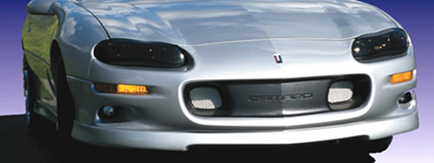
Front Fascia
This front fascia from DG Motorsports is a cheap and simple upgrade to make if you're looking to improve the aesthetics of your muscle car. With an extended front air dam, the front end looks as if it hugs the ground, and it helps maintain ideal aerodynamics during spirited driving. Ready to paint, no sanding or prepping required, and it's available at Andy's Auto Sport for a reasonable $189.95 a piece:
PERFORMANCE EXHAUST SYSTEMS
Magnaflow
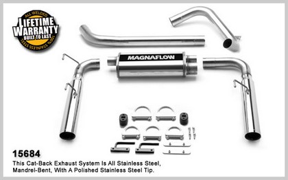
Dual Split Rear-Exit, Catback
Magnaflow's catback exhaust systems are sturdily built and easily installed. With promises of increased torque and horsepower, sharpened throttle response a throaty burble and a distinctive look with two wide exhaust tips sticking out from the rear bumper. Available through Andy's Auto Sport for a very reasonable $559.47, which includes shipping:
FIREBIRD HOODS
VIS Racing
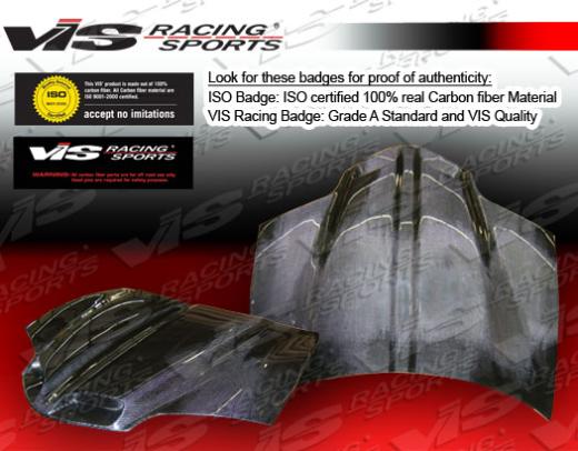
GTO Style Carbon Fiber Hood
VIS Racing's line of carbon auto parts is a great way to improve the performance and fuel economy of your Firebird without breaking the bank. Plus, they look great. This particular GTO-style hood has two massive intakes to help funnel cool air into the engine bay. Also, these hoods are so light, in fact, that the best way to secure them is with a set of hood pins, another auto part that is available, along with the hood itself, through Andy's Auto Sport:
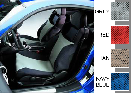
SEAT COVERS
Covercraft
Seat Gloves
Covercraft brings some of the best design seat covers to the table with their SeatGloves, which have Coolmax fibers that are placed on top a 1/8 inch thick D3 warp knit spacer fabric to wick moisture a assure breathability so you won't have that hot, wet, sticky feeling like you do with neoprene seat covers! Semi-custom patterned for bucket seats, SeatGloves high-performance Coolmax seating panel assures you stay comfortable - helping you drive better. Available in 5 colors from Andy's Auto Sport at the reasonable price of $160.64: